
Before the design of a probe can even start, especially for applications requiring custom designs, there are several things to take into consideration. Our job, of course, is to make them disappear as much as possible so that, for you, choosing a probe is as straightforward and painless as possible.
It’s still a good idea to understand what influences probe design once you’ve told us about the elements outlined in Stefan Parmentier’s 10 Things You Must Know to Choose the Right ECA Surface Probe and Marc Grenier’s 6 Things You Must Know Before Inspecting Tubes.
Through a very organic process, we weigh the various impacts of the elements below to reach the compromises necessary to achieve the goals set for the probe:
- Coverage
- Noise
- Sensitivity
- Signal-to-noise ratio (SNR)
- Topology
- Mechanical design
- Scan speed
Let’s look at each one.
This term is a bit loaded. It’s often strictly (and mistakenly!) associated with the physical area covered by a probe or the array of coils. Coverage is much more than a mere physical area — it involves a mix of the:
- Width of the array of coils (of course!)
- Three-dimensional shape of the array’s sensitivity profile
- Maximum and minimum sensitivity
- Relation between the acquisition rate and scan speed
- Frequency of the alternating current flowing in the coils of the array
All these elements combine to yield the effective area within which defects can be detected and characterized, if necessary.
That’s coverage.
Before detection and characterization can begin, we must ascertain the amount of noise that will be present in the inspection signal. This allows us to determine whether the noise can or needs to be compensated for or filtered out.
There are two categories of noises: intrinsic and extrinsic, and each type of noise can be categorized as such.
Intrinsic Noise
It is caused by the nature of the material under test (variations in properties such as conductivity and permeability). We can operate some control over intrinsic noise through a combination of magnetic saturation, topology (see below), and post processing. The point is, however, that intrinsic noise is always present and must often be mitigated.
Extrinsic Noise
This relates directly to the design of the probe, among other external factors. For example, extrinsic noise can emanate from cables, interference, resonance, etc. Similarly, at the high end of the AC frequency range, the inductance of coils can resonate with their parasitical capacitance, the probe’s cable, and the test instrument, which leads to overamplified and distorted signals.
Other instances of extrinsic noise come from the power grid and the capacitor noise generated by the movement of the probe’s cable. The entire inspection system (combination of test instrument, cable, and probe) is also known to generate its own specific noise.
Having a good understanding of the level of noise allows us to establish the acceptable defect SNR for the application to yield clear results.
This can be defined as the ability of a probe to generate enough eddy currents to be disturbed by defects and its ability to detect them—to measure the strength of the signal generated by defects.
In non-destructive testing, SNR is the measure comparing the defect signal and the noise signal (intrinsic and extrinsic). A ratio higher than 1:1 (greater than 0 dB) indicates more signal than noise, which is a must.
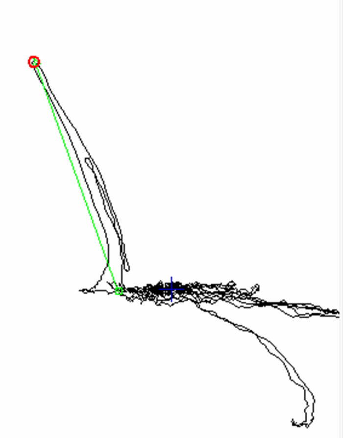
Offsetting the defect phase and/or frequency from the noise’s phase and/or frequency is a good way to get an effective SNR. Therefore, we always aim to design probes with the highest possible SNR according to the situation.
Here, you can see that the detected defect is clearly offset from the noise, making it easy to see.
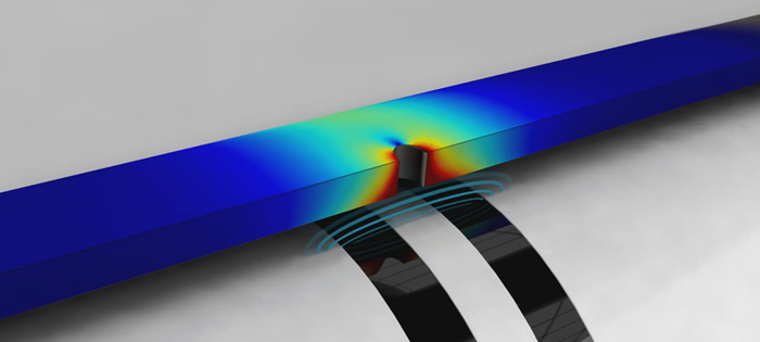
These are the combinations of coil arrangements and their activation patterns, used in creating at least one eddy current channel (i.e., 1 timeslot + 1 input). Topologies usually comprise two coil rows to generate a good sensitivity profile to defects, but some situations may call for more rows.
Here is an example of how coils in a single-driver topology are activated during a given timeslot. T stands for transmitter and R for receiver.
The conditions under which the probe will be used is key to its mechanical design. Surface or tube conditions, environmental conditions, automation, cable length, physical access, as well as defect location and orientation all influence the mechanical design.
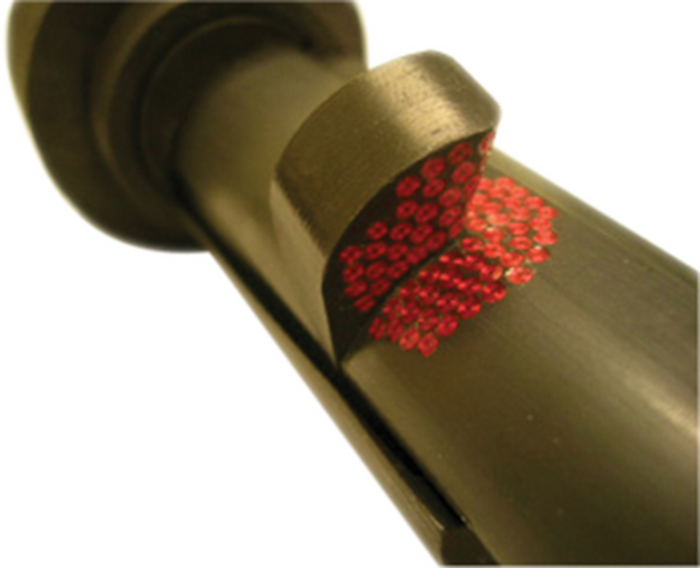
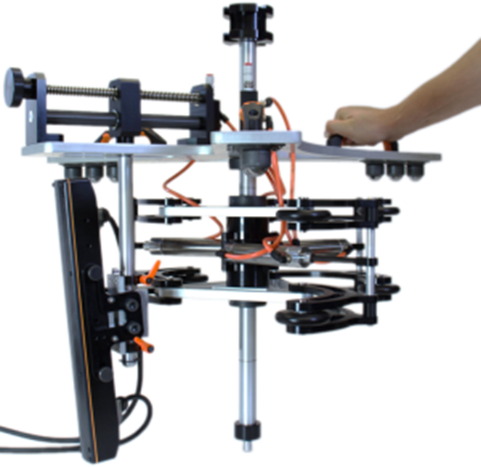
Other key factors are chemical requirements (such as in nuclear plants), which impact the choice of materials used in designing the probe. Manufacturing methods can have an influence. Here are a few examples of innovative mechanical designs.
Stainless Steel Cladding Weld Inspection Solution
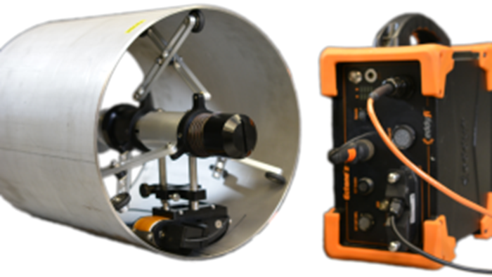
Borehole Inspection Solution
The effective number of eddy current channels in relation to the acquisition rate of the test instrument gives us an indication of the scan speed. However, one must take into account the mechanical logic of certain calculated speeds; even if you can achieve a scan speed of 5 m/s (16 ft/s), if the part under test or its defects are small by comparison, this speed may make little sense. In such a situation, we would lower the sampling rate while still maintaining an SNR optimized for a speed that makes more sense from a physical standpoint.
As you now understand, balancing the combination of all the above factors is quite a juggling act that is entirely about compromise. We will cover most of these elements in more depth in upcoming blog posts, which will make the compromises even easier to see.
In the meantime, swing back to our Website to see the various probes and test instruments we have to offer. You could also go back to Eddies and Currents to read more articles about the stuff we do.