
With known dead zones in tube inspection around carbon steel support plates, it’s important to make sure that you’re choosing the right probe for maximum coverage and reliable results ultimately used for efficient asset integrity health management programs. This article takes a look at how double-driver and double-receiver Remote Field Testing, or RFT, probes are impacted by tubesheets to detected defects.
Single Driver Standard (SDST) remote field testing probes are the classic RFT probes for inspecting ferromagnetic tubes in which a transmitter coil excited at a low frequency generates a magnetic field. The receiver coils are located at an axial distance corresponding to more than 2.5 times the diameter of the probe, in the so-called "remote field" zone where the magnetic field has passed through the tube wall twice: from the inside to the outside and then outside to inside. The attenuation of the field is measured, and a lower attenuation corresponds to a lack of material.
Since carbon steel support plates block this field, "dead" zones where detection is limited are located on both sides of the position of these plates. These zones are conducive to the appearance of defects. It is therefore advantageous to minimize the dead zone.
Another type of conventional probe was designed to overcome this limitation to some extent. Dual Driver Standard (DDST) probes have receiver coils in the center of the probe and two generators at the probe head ends. This reduces the dead zone: rather than extending the entire distance between the generator and the pair of receivers on either side of the plate, one can use the sensitivity on one side of the plate using the first generator, and then on the other side using the other generator. There is still an effect since one of two generators remains blocked which affects the signal compared to the "free" areas where the combined fields of both generators are sensed at the same time.
Single Driver Dual Receiver (SDDR) probes are a second type of probe whose configuration was designed to further reduce the dead zone. The SDDR probe consists of a single, shorter generator coil located in the center of the probe with two pairs of receivers on either side. Since there is only one generator, the receivers on either side receive the entire signal as soon as the generator has left the zone of influence of the plate, leading to a smaller affected detection zone.
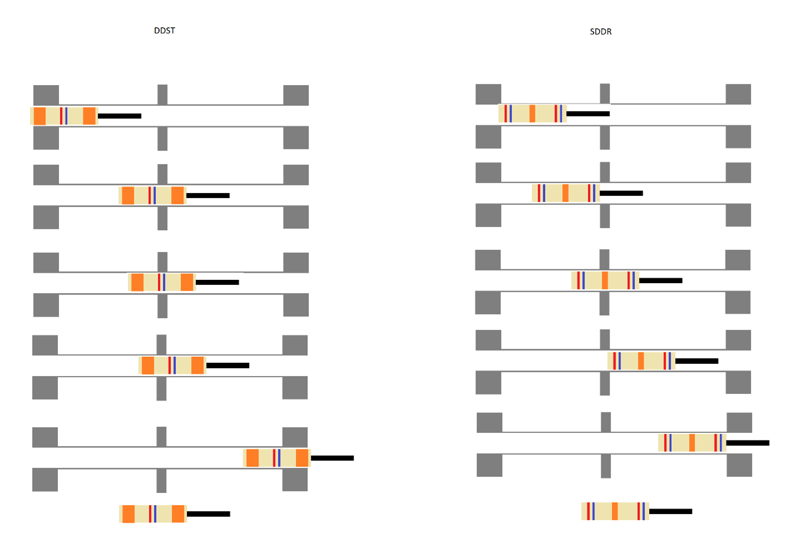
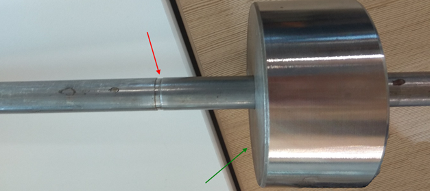
To illustrate this behavior, a study on the coil configuration’s effect to defect detection based on tubesheet distance was performed. A moving tubesheet was installed on a reference tube at different distances from the defect of interest, and the tube was inspected by the SDDR and DDST probes. The results shown are for a short 3.175-millimeter (0.125-inch) long, 20% WT-deep OD groove in a 19.05-millimeter (0.75-inch) OD, 2.11-millimeter (0.083-inch) thick carbon steel tube.
These results are not necessarily calibrated but are used to show the shape and position of the signal and general behavior obtained based on the probe type.
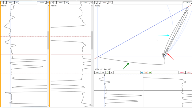
Below is an example of data for the SDDR with a 30-millimeter (1.2-inch) gap between the plate and the short 20% OD groove. The plate signal is pointed to in green, the signal of a wider 20% OD groove is pointed to in light blue, and the signal of the 20% short groove is pointed to in red. The phases are similar for both 20% notches in this case. Note that this wide groove creates a twin signal created by passing over the driver and receiver coils.
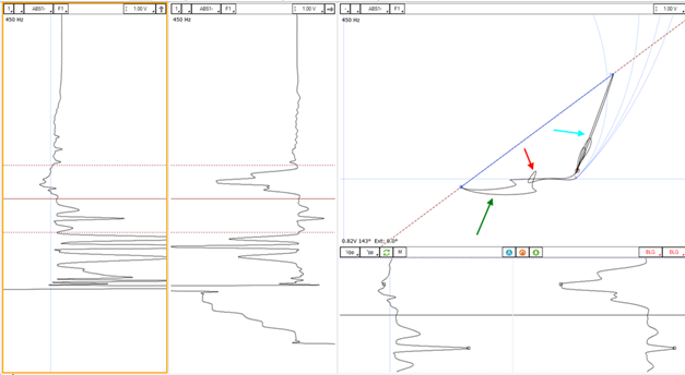
Below is an example of data for the DDST with a 30-millimeter (1.2-inch) gap between the plate and the short 20% OD groove. Again, the plate signal is referenced by the green arrow, the signal of a wider 20% OD groove by the light blue arrow, and the signal of the 20% short groove by the red arrow. The phases are similar for the two 20% notches, but the signal for the 20% short notch is much more difficult to identify and measure correctly since it is superimposed on the plate signal. Note that this wide groove creates a triple signal from passing over each driver (smaller bumps) and receiver coils.
The short 20% OD groove was placed different distances from the tubesheet and examined. The tubesheet signal is always pointed to in green, the groove in red. The indication of whether or not the defect was detected is not binary. It is a continuum from clear detection to non-detection through probable or improbable detections considering whether the defect signal is superimposed on the plate signal and how distorted the defect signal is and therefore its phase difficult to measure. The distinction may seem arbitrary but is mainly used for comparison purposes between both probe signals.
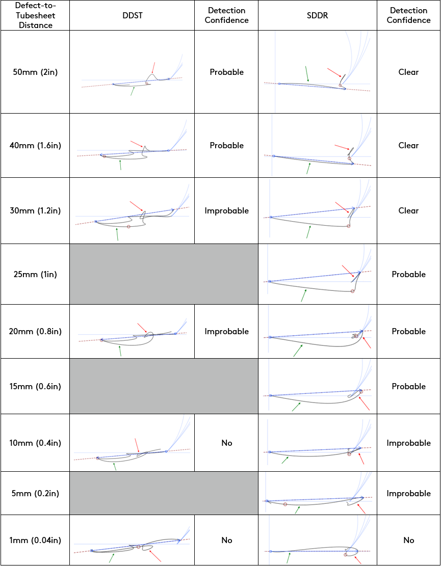
It can be concluded that with the dual driver probe, the defect is already superimposed on the plate signal at a 50-millimeter (2-inch) distance whereas this behavior occurs at a 25- or 30-millimeter (1- to 1.2-inch) distance with the dual receiver probe. Likewise, the improbable detection level —with a phase sufficiently affected and difficult to measure or a higher signal shape distortion— is reached at a 30-millimeter (1.2-inch) gap for the DDST and at 10 millimeters (0.4 inches) for the SDDR. There is therefore an improvement of about 20 millimeters (0.8 inches) for the minimum near-plate detection distance for an SDDR probe compared to a DDST probe, at the cost of needing to analyze two receiving channels rather than just one.
Eddyfi Technologies offers a range of non-destructive testing technologies to cover a multitude of applications. Another option for inspecting carbon steel tubes under tubesheets or support plates is our IRIS ultrasound rotary inspection system. While slower and requiring water as a couplant, this technique does not depend on the transmission of a magnetic field through the tube wall or support plates and can therefore detect and dimension defects at these critical positions.
Check out our online tool for finding the right tubing probe here.
We invite you to contact our team of NDT experts to better understand the ideal Beyond Current solution for your particular application for the best results.