
We have been monitoring the situation very closely and are working with our important client base to understand if technology efficiency can help with the potential demand in integrity assessments of aging storage facilities.
This article outlines some best practice inspection programs, courtesy of Oceaneering and their tank integrity and inspection department, that can help increase confidence in bringing storage facilities back online.
RISK-BASED ASSESSMENT
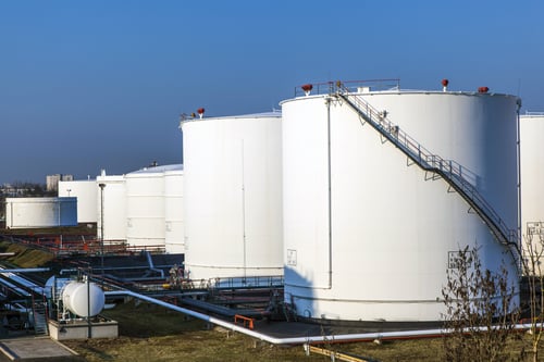
Every above-ground storage facility will have individual needs and requirements when it comes to integrity inspection, and it is important to work with qualified mechanical integrity engineers to develop a written scheme of examination. An experienced engineer will be able to assess the product type, historical conditions, construction information, and years-in-service to perform a risk-based assessment (RBA) of the offline asset.
It is during this initial assessment that knowledge of inspection technology can help make better decisions. The examination is split into a sequence of identified integrity risks, and each component of this inspection can be aided with the correct technology selection.
RECOMMENDED TECHNOLOGY
As discussed, each tank inspection is unique and although the following inspection protocols are industry recognized, it is important to consider the information within the RBA before implementation.
Internal Floor/Annular/Sketch Plates
A common failure mechanism is leakage through the floor that damages the tank foundation, leading to instability and possibly resulting in catastrophic failure. The most common technology used to inspect tank bottom plates for corrosion is magnetic flux leakage (MFL) because of its sensitivity to volumetric variations.
MFL uses a strong magnet to induce a magnetic field in the bottom plate. When it encounters corrosion of a certain size, the magnetic field “leaks”. The more critical the proportional volumetric rate, the higher the leakage.
Leakage is detected by a combination of several types of sensors. On its own, MFL technology is incapable of detecting whether defects are on the top or bottom side of plates. For this reason, Eddyfi Technologies combines MFL with surface topology air-gap reluctance Sensors (STARS). This enables the mapping of storage tank floors with the critical benefit of determining if the corrosion is topside or soil side.
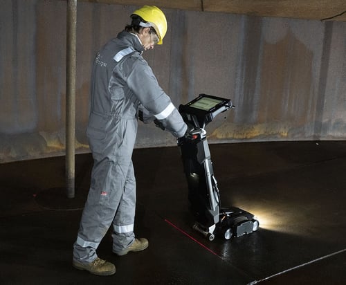
The Floormap®X offers an unmatched probability of detection, including in the critical zone, and can address thick plates and coatings with ease. It provides complete floor mapping with unprecedented efficiency.
Combining the two scanners reduces the time it takes to inspect tank floors while producing detailed and accurate reports, enabling engineers to determine optimum maintenance strategies.
Shell and Roof
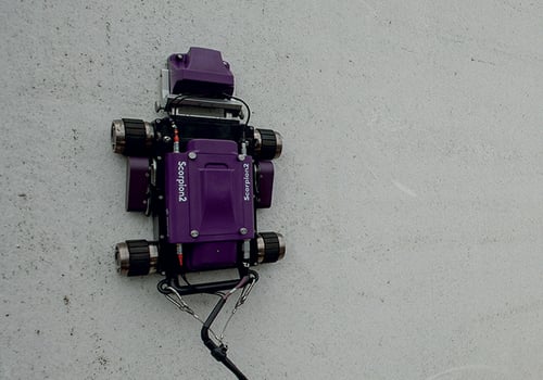
The most common method used to determine the condition of a tank shell or tank roof is with a remote access ultrasonic testing (UT) crawler. They are typically designed to perform cost-effective UT thickness measurements without the need for scaffolding or rope access.
UT crawlers can operate automatically or manually. They perform line scans on the tank shell surface or scan specific areas, including the roof. In most cases, tank shells are divided into 8, 16, or more equal sections as specified by the inspection regulation. B-scan UT data is recorded for each section from bottom to top, showing the condition along each course. The speed of the UT crawler and the data acquisition rate plays a significant role in the efficiency of tank wall surface inspections. The battery powered Scorpion® 2 crawler can travel and inspect up to 180 millimeters per second (7 inches per second). Other system features include a dry-coupled wheel probe which eliminates the need for the complex water supply system usually associated with UT inspections. A simple probe setup procedure and floating and tracking UT gate results in a more accurate and reliable integrity assessment.
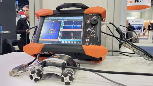
Phased array ultrasonic testing (PAUT) corrosion mapping has become more prevalent in recent years when a more detailed inspection is required or there is a need for further investigation of a particular area of concern.
Phased array probes have a wide electronic footprint, and with a 1 mm (0.04 in) resolution across the width of the beam, the required scanning coverage is achieved in significantly less time. The ability to collect high-resolution data at increased scanning speeds improves the probability of detection, enhances imaging, and improves defect characterization.
Photo c/o Jonathon Edgington
Our automated corrosion mapping scanners high-resolution robotic crawler is up to 10 times faster than conventional corrosion mapping at a 1 x 1 mm (0.04 × 0.04 in) resolution.
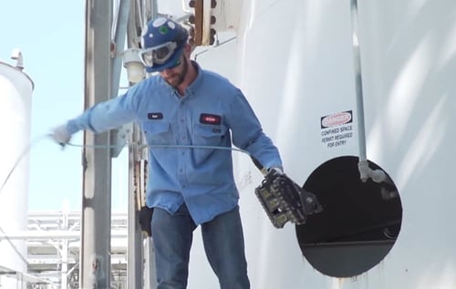
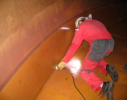
Visual Inspection of All Critical Components
It is recommended to conduct a visual inspection of all critical components to identify problems and perform repairs before a significant leak occurs. Maintaining these critical components is key. Therefore, remote visual inspection (RVI) with robotic crawlers like the quickly deployed VersaTrax™ M-Series (formerly known as the MaggHD™) provides data in real-time without the need for expensive scaffolding or rope access. The STIK™ is a turnkey tank inspection kit equipped with an automated scanning capability that offers full 360-degree internal tank inspections, including assessment of liners, welds, fasteners, and defects.
Full Crack Detection of Annular Internal and External Welds and Percentage Floorplate Welds
The alternating current field measurement (ACFM®) technique was specifically developed to detect and size surface-breaking defects at welds and can work through several millimeters of non-conductive coating. Recognized by API, ACFM with instruments like the Amigo™ 2 is a natural choice for inspecting storage tank welds and can be used in lieu of magnetic particle inspection (MPI) to avoid expensive surface preparation and consumable chemicals.
ACFM is an electromagnetic inspection technique that introduces an alternating current into the surface of a component to detect surface-breaking cracks.
The presence of a crack disturbs the electromagnetic field, and the return signal is instantaneously converted by advanced mathematical techniques so that operators are alerted to the presence of defects.
Tank Annular Rings
UT and pulsed eddy current (PEC) can reliably detect corrosion in annular rings from outside storage tanks. More specifically, it’s possible to perform this with the Pulsed Eddy Current Tank Floor Probe while tanks are in service. PEC sensors are designed to tolerate liftoff between the surface under test such as air, soil, water, concrete, asphalt, and corrosion products. Probes designed specifically for this type of inspection also exist. One such probe has a thin 4.8 mm (0.2 in) titanium blade that can slide up to 400 mm (16 in) under above-ground storage tank annular rings, enabling it to assess the remaining wall thickness of this critical component exposed to corrosion. The probe sensor can tolerate up to 13 mm (0.5 in) of liftoff, and software features optimize thickness measurements, which ensure the best performance and repeatability.
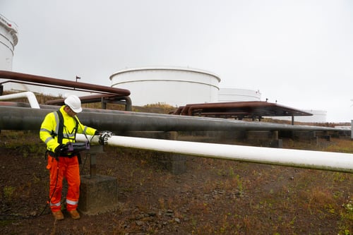
Associated Pipe Equipment
Pipework associated with tank storage facilities are often inspected for corrosion and pitting. The typical diameter range is from 100 to 400 mm (4 to 16 in), and thickness measurement locations are identified to assess remaining wall thickness and calculate corrosion rates through periodic inspection.
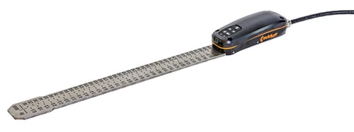
The Pipescan HD is an MFL inspection tool that has been specifically developed to rapidly inspect lengths of pipework and identify areas of corrosion and pitting that can be later quantified with visual inspection or UT.
The Pipescan HD is the highest resolution MFL scanning tool on the market and, with a color palette touchscreen display, has unrivaled competition for probability of detection and defect characterization. Under the correct circumstances, Pipescan HD can reliably detect corrosion pits with dimensions as little as 1 x 2 mm (0.04 x 0.08 in) and productivity can be as much as 250 m (820 ft) in four hours of inspection.
MFL is a semi-quantitative inspection technology and although defect severity can be assumed with the correct calibration process, operators will often complement their Pipescan HD inspection with phased array corrosion mapping. Automated corrosion mapping systems are the perfect supplement to MFL and can provide fully quantitative information and recordable data sets. Our solutions in conjunction with our phased array instruments, creates a fully portable solution that can collect high-resolution phased array data without the need for power or permanent water supply.
The implementation of advanced NDT solutions for tank inspection and more importantly, bringing tanks back online amid a fuel storage shortage, is critical. Eddyfi Technologies offers a wide range of proven solutions to optimize this process, and we invite you to contact our friendly experts today for more information.