Explore Eddyfi Technologies Product Lines
High Performance IRIS Testing of Heat Exchanger Tubes
Ask an expertInspecting tubes with an Internal Rotary Inspection System (IRIS) is one of the oldest heat exchanger tube wall loss measurement techniques around. IRIS inspection is based on ultrasonic Time of Flight (ToF) to ascertain the remaining wall thickness in tubes.
The Challenge
IRIS tube testing is powerful but complex, sensitive to pull speed and centering, and is of limited effectiveness in thin-walled tubes.
Heat exchanger tubes are often scanned using one inspection technique, and then reinspected with another to confirm the remaining wall thickness. IRIS testing is often used as a secondary technique.
IRIS testing in ferrous and non-ferrous heat exchangers can detect a variety of defects:
- ID/OD pitting in tubes and at support plates
- Erosion caused by the fluid flowing inside and outside tubes, and turbulence at tube inlets
- General tube wall thinning
However, tube inspection with IRIS has the following limitations:
- Heat exchanger tubes must be flooded with filtered water making the inspection setup complex and difficult to use.
- It is sensitive to ID/OD deposits and fins, which are not defects.
- It is unable to detect cracking.
- It has a hard time assessing through-wall defects because they look like missing data.
- It is slow compared to electromagnetic inspection techniques.
- Deep defects lead to false calls, mainly in thin tubes.
When it comes to sizing, IRIS testing is limited. For example, in 25.4 mm (1 in) diameter, 3 mm (0.12 in) thick carbon steel tubes (some of the most common tubes in heat exchangers), the deepest defects conventional IRIS testing can detect are 66% of the tube thickness. This is because the average IRIS defect detection limit is 1 mm (0.04 in), making deep defects in thinner tubes impossible to size.
Furthermore, IRIS testing detection and sizing accuracy (by extension) rely heavily on the pull speed. An IRIS probe’s turbine rotation yields helical scans. Depending on the ultrasonic beam’s diameter on the tube’s inner surface at the focal point (typically 0.5–1.0 mm [0.02–0.04 in]), covering the entire inner surface of tubes with such a scan is achieved at pull speeds ranging between 40–50 mm/s (1.5–2.0 in/s) in a 25.4 mm (1.0 in) outer diameter tube. Increasing the speed reduces coverage, leading to loss of data.
The accuracy of IRIS inspection results also greatly depends on the probe’s centering. Sure enough, heat exchanger tubes are dirty, affecting the ultrasonic beam’s angle of incidence, which needs to be as close as possible to the normal to be effective.
The Solution
Improved IRIS inspection system less sensitive to pull speed and centering, with a better effectiveness in thin-walled tubes.
A better IRIS inspection solution must therefore offer better detection and sizing performances, therefore less dependence on pull speed and better centering.
The IRIS inspection solution features patent-pending impedance matching, which can reduce the defect detection limit to 0.8 mm (0.03 in), increasing the detection limit to approximately 80% of the tube thickness, making sizing deep defects in thinner tubes possible.
The Ectane® test instrument uses an above-industry-average 180 acquisitions/rotation, making pull speeds of 100 mm/s (4 in/s) possible. This is almost twice as fast as most other systems, meaning the IRIS inspection solution is less influenced by pull speed variations.
Further, the IRIS inspection solution is equipped with high-quality spring-loaded centering devices that are guaranteed to deliver near-perfect centering, improving the quality of results.
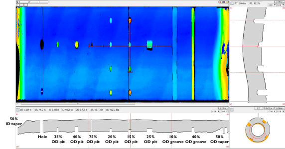
The Magnifi® acquisition and analysis software is designed to make it easy to set up all the combined and realtime IRIS inspection views (A-scan, C-scan, and projection). Magnifi C-scans allow easily identifying and sizing the various types of defects found in heat exchanger tubes with greater accuracy than with other systems.
Learn moreBenefits
- Faster IRIS inspection less sensitive to pull speed variations, with better detection performance and accuracy.
Using the IRIS tube inspection solution has the following benefits:
Faster than other IRIS inspection solutions
The Eddyfi Technologies' solution can be pulled at about twice the speed of others, thanks to Ectane’s higher acquisition rate.
Less sensitivity to pull speed
The faster acquisition rate makes IRIS inspection solution less sensitive to pull speed variations.
Better detection performance
Better centering stabilizes the UT beam and patent-pending impedance matching technology improves performances in thin-walled tubes.
Intuitive imaging
Magnifi imaging is more intuitive, making it easier for operators without extensive IRIS tube inspection knowledge to identify and size the various types of defects found in heat exchanger tubes with greater accuracy than with other systems.