Explore Eddyfi Technologies Product Lines
How to Better Assess TY Fillet Welds with Actionable Insights
Ask an expertTKY joints are widely used across different construction sectors in storage tanks, naval components, bridges, and more. A failure in a fillet weld may lead to heavy loss or wastage of materials contained by a tank, or it may have other major consequences to the fitness-for-purpose of assets. Given their complex geometry, T-joints and similar weld geometries have always presented a challenge for ultrasonic testing, yet validating their integrity remains necessary.
The Challenge
Identify a better solution for performing condition assessment of TKY joints known to be problematic during ultrasonic testing.
Traditional ultrasonic testing of fillet welds has always been possible but somewhat impractical due to the geometry of the joint. While standards give guidance on how to realize the proper scan plan to inspect TKY joints, achieving complete coverage can sometimes be problematic.
When access permits, the preferred technique is from the plate opposite the web using a combination of zero-degree linear scan and sectorial scans perpendicular to the bevels. Unfortunately, accessibility is sometimes an issue, and the operator may need to inspect the joints from other surfaces.
Undesirable, or repetitive, echoes coming from various places of the joint make analysis complicated and tedious. This leads to lower efficiency, and a lower probability of detection.
An alternative to this technique is using refracted shear wave S-scans or E-scans from the web side of the flange surface. More than one standoff position may be required for thicker sections. Examination from both sides of the web plate should be used when access permits. Phased array scanning procedures require the definition of a scan plan that shows full volume coverage and appropriate beam angles.
The Solution
An advanced software solution validates that coverage is adequate and reduces the adverse effects of this weld configuration.
A complete software tool available within Capture™ allows the definition of TKY joints. This tool makes it easy to calculate the optimum scan plan directly on the portable phased array ultrasonic testing equipment to guarantee complete coverage of the welds.
The embedded software allows operators to position their probe on any surface of the joint and calculate scan plans with any type of probes: linear, matrix, dual linear array, dual matrix array. By selecting the correct index offset and the proper delay laws, operators can ensure full coverage of the weld. When focusing, it is possible to optimize the position of the focusing points and thus optimize the sensitivity of detection of indications positioned along the bevels.
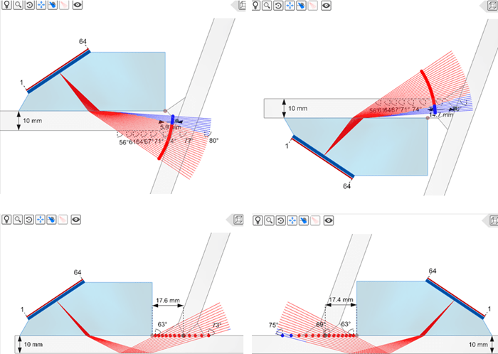
Request a quoteThe following images show scan plans for a position on each surface of a Y welded joint. The ray tracing together with annotations such as the refracted angles, thickness, and index offsets allow operators to see coverage of the welded joint. Near field information indicated by the two colors of the rays indicates to operators whether they can focus the beam on the intended location.
Sectoral or linear scans are displayed in real time and superimposed to the 3D component to evaluate the effectiveness of the delay laws, allowing the operator to modify them on the fly and properly adjust the angles and focusing parameters.
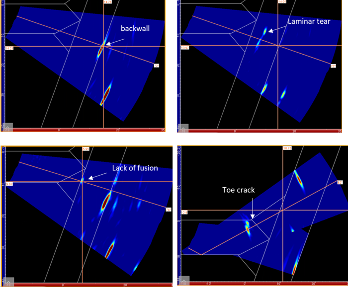
The following images show sectorial scans for four different locations superimposed on the overlay, in white, on the Y weld. The top left image shows a sectorial scan with no defect. The alignment of the echo with the backwall of the overlay indicates that this echo is a geometric echo and not a defect one. The three other images show a laminar tear, lack of fusion, and a toe crack, respectively. Their position along the overlay helps operators interpret the nature of the defects and thus their gravity to the integrity of the structure. It is worth noting that the sectorial scan for the toe crack was reconstructed after a rebound off the opposite surface to allow correct positioning of the toe crack echo. Capture allows as many reflections as an operator wants.
Analysis tools such as autosizing and 3D export are available for TKY joints to help operators characterize indications. The following video shows the analysis of a Y welded joint using the autosizing feature and the export of the data in the 3D view of the component.
Learn moreBenefits
- Precise visual representation of real-time conditions enables confidence in technicians and more informed decisions by owners and operators.
Cross-section overlays are calculated and superimposed with ultrasonic data making it possible to precisely position and size indications. It is also possible to account for rebounds off the various surfaces of the joints.
Eddyfi Technologies proposes a unique solution for the ultrasonic inspection of TKY joints commonly found in the oil and gas, metallurgy, and marine industries. This solution helps operators set their scan plans per code, simplify inspections and analysis, saving overall time while improving the safety of assets under assessment.